What’s The Difference Between Wiring Batteries In Series Vs. Parallel?

What's The Difference Between Wiring Batteries In Series Vs. Parallel?

Batteries don’t fail because of chemistry alone — they fail because of how they’re connected. One small wiring decision can change system voltage, current, heat generation, charging behavior, and even battery lifespan. Yet many people still think series vs. parallel is just a simple “voltage vs. capacity” choice. In real systems — solar, RV, marine, backup power, or electric vehicles — the way batteries are connected directly affects safety, efficiency, and long-term reliability. This guide explains series and parallel connections in clear, practical terms, so you can design or wire a battery system that actually works the way you expect in the real world.

1. Introduction: Why Battery Connections Matter More Than You Think

If you spend five minutes on battery forums, you’ll see endless debates about cell chemistry and cycle life. But in the field, I rarely see batteries fail because the chemistry was bad. I see them fail because the wiring was sloppy.

You can buy the most expensive Grade-A lithium cells on the market, but if you connect them with undersized cables, loose lugs, or the wrong topology, you are building a fire hazard, not a power system.

This guide isn’t about memorizing formulas. It is about the physical reality of moving high current through metal and how to do it without melting your rig.

1.1 One wrong connection can damage batteries or equipment

When we talk about “bad connections,” most people think of a system that simply doesn’t turn on. If only it were that simple.

A poor connection creates resistance. When you push high current through resistance, you generate heat. In a 12V or 24V system where currents are high (often 100A+), a loose terminal nut isn’t just an annoyance; it’s a heating element.

Real-world consequences of poor wiring:

  • Voltage Drop: Your inverter cuts out early because it “thinks” the battery is dead, even when the battery is full. The voltage is being lost in the wire, not the cells.

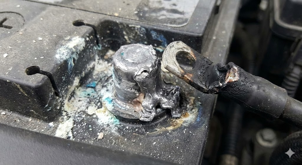
  • Terminal Burnout: Heat concentrates at the loose point. I’ve seen battery posts melted into slag because a washer was placed in the wrong order.

  • BMS Failure: Incorrect series wiring can expose a low-voltage Battery Management System (BMS) to high-voltage spikes, frying the electronics instantly.

  • Arcing: In severe cases, DC electricity can arc across gaps, welding contacts together or starting electrical fires.

1.2 Series vs. parallel is not just "voltage vs. capacity"

The textbook definition is simple: Series increases voltage; Parallel increases amp-hours.

But from an engineering standpoint, the choice changes everything about how you manage the bank.

  • In Series: You have to worry about balance. If one battery drifts lower than the others, it becomes a bottleneck and can even be reverse-charged by the stronger batteries. You need specific balancing gear.

  • In Parallel: You have to worry about current sharing. If wires aren’t perfectly equal in length, the battery closest to the load does all the work and dies early, while the furthest battery sits idle.

Choosing between them isn’t just about hitting 24V or 48V; it’s about choosing which management problems you are willing to solve.

1.3 Who this guide is for (DIY, solar, RV, EV, OEM systems)

I wrote this for the people who actually have to bolt these things together and sign off on the safety.

  • DIY & Off-Grid Builders: You are building a van, boat, or cabin system and don’t have a corporate engineering team to double-check your work.

  • Replacement Buyers: You are swapping old lead-acid blocks for new Lithium Iron Phosphate (LiFePO4) and need to know if your old cables will burn up.

  • OEMs & Integrators: You are building small fleets of custom power systems and need a standard operating procedure (SOP) for your technicians.

1.4 What you will learn in this guide

We are going to skip the electro-chemistry and focus on the electromechanical assembly.

By the end of this guide, you will know:

  • The Physics of Connections: Why torque specs and cable crimps make or break a system.

  • Series vs. Parallel: Detailed wiring diagrams and the specific risks of each.

  • The “Diagonal” Take-off: The single most important wiring trick for parallel banks that most beginners miss.

  • Protection: How to size fuses so they blow before your wire insulation melts.

  • Voltage Mismatch: What actually happens when you connect a full battery to an empty one (and how to avoid the spark).

2. Battery Basics You Must Understand First

Before we start bolting cables together, we need to clear up the terminology. In the field, mixing these terms up leads to expensive mistakes. I’ve seen customers buy “powerful” batteries that couldn’t start their engines because they confused capacity with current.

We will keep the physics light, but you need to grasp these four concepts to build a safe system.

2.1 Voltage (V) — electrical pressure

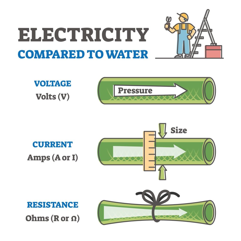
Think of voltage as electrical pressure. It is the force that pushes electrons through your wires.

If you have a narrow pipe (a thin wire) and you try to push a lot of water (current) through it with low pressure, nothing moves fast. If you crank up the pressure (voltage), you can move that same water much faster.

Practical Rule of Thumb:

  • System Match: Your battery voltage must match your equipment. You cannot hook a 24V battery bank to a 12V inverter; you will fry the inverter instantly.

  • State of Charge: Voltage is also your gas gauge. A “12V” lead-acid battery is actually at 12.8V when full and 11.8V when empty. If it reads exactly 12.0V, it’s already dangerously low.

2.2 Capacity (Ah) — how long the battery can supply power

Amp-hours (Ah) measure the size of your fuel tank.

If you have a 100Ah battery, in theory, you can pull:

  • 100 Amps for 1 hour

  • 10 Amps for 10 hours

  • 1 Amp for 100 hours

The “Usable” Capacity Trap: This is where chemistry matters.

  • Lead-Acid/AGM: You should generally only use 50% of the rated capacity to prevent damage. A 100Ah AGM battery only gives you 50Ah of real-world use.

     
  • Lithium (LiFePO4): You can use 80–100% of the capacity. A 100Ah Lithium battery gives you nearly 100Ah of real use.

When you buy a battery, don’t just look at the sticker number. Ask yourself: “How much of this can I actually use before the voltage sags too low?”

2.3 Energy (Wh) — the real measure of stored energy

This is the number that actually matters when comparing different systems.

Amp-hours are confusing because they depend on voltage. Is a 200Ah battery “bigger” than a 100Ah battery? Not if the 200Ah is 12V and the 100Ah is 48V.

To get the true energy storage, we use Watt-hours (Wh). Formula: Voltage (V) × Capacity (Ah) = Energy (Wh)

Comparison Example:

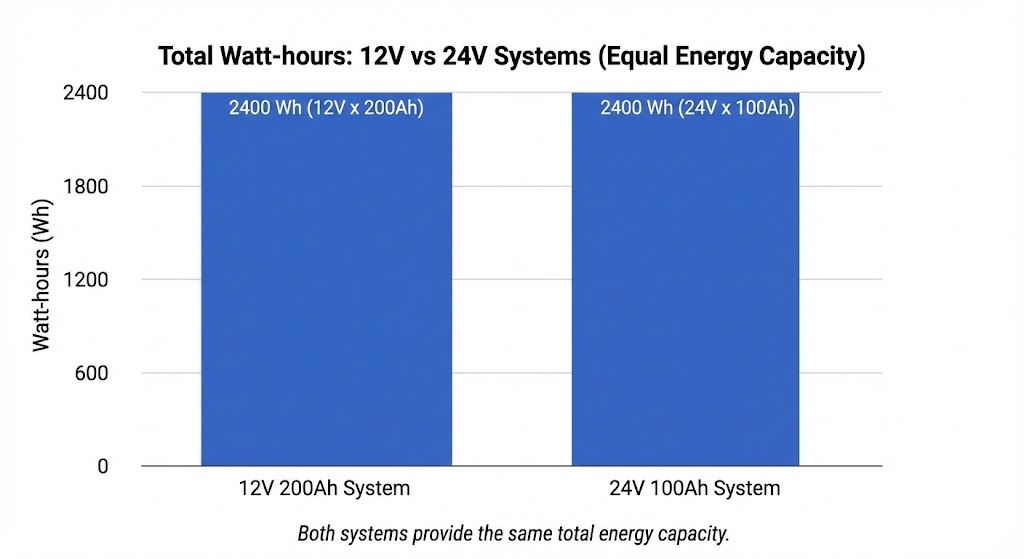
  • Battery A: 12V × 200Ah = 2,400Wh

     
  • Battery B: 48V × 100Ah = 4,800Wh


Battery B holds twice the energy, even though the “Ah” number is smaller. When sizing a system for solar or backup power, always calculate your daily consumption in Watt-hours, then size your battery bank to match.

2.4 Why voltage and current both affect system design

This is the most critical engineering decision you will make: Choosing your system voltage.

Power (Watts) is Voltage × Current. To get the same power, you can either have high voltage and low current, or low voltage and high current.

Why High Current is the Enemy: Current creates heat. To handle high current safely, you need:

  • Thicker, more expensive copper cables (like 4/0 AWG).

     
  • Heavier lugs and fuses.

  • More robust connections to prevent melting.

The Voltage Advantage: By doubling your voltage (from 12V to 24V), you cut the current in half for the same power output.

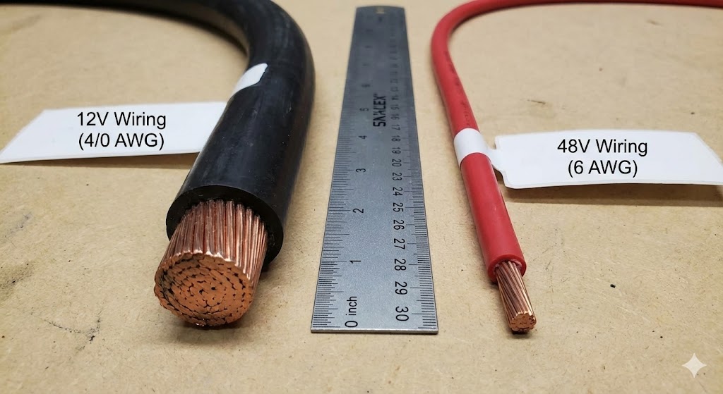
  • 12V System: Running a 2000W microwave requires ~166 Amps. This needs massive cables (4/0 AWG).

     
  • 48V System: Running that same 2000W microwave requires only ~41 Amps. You can use much thinner, cheaper wire (8 AWG or 6 AWG).

Engineering Recommendation:

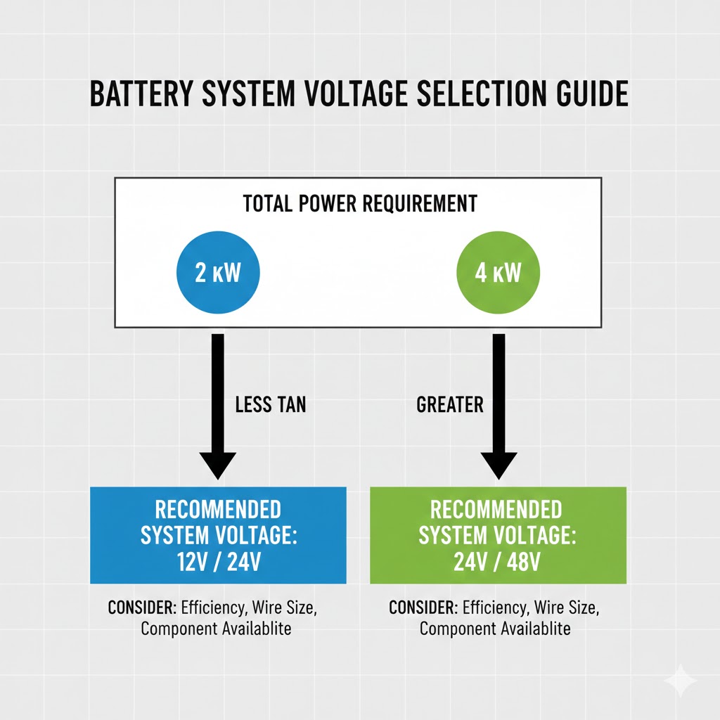
  • 0 – 2,000 Watts: 12V is fine (RV, small boat).

  • 2,000 – 4,000 Watts: Go to 24V.

  • 4,000+ Watts: You must go to 48V. Dealing with 300+ Amps at 12V is dangerous and impractical.

3. What Does Connecting Batteries in Series Mean?

Series connections are the backbone of higher-power systems. If you need to run a 24V trolling motor or a 48V whole-home solar system, you cannot do it with a single 12V block. You have to stack them.

Connecting in series increases the electrical pressure (voltage) without increasing the size of the fuel tank (capacity).

3.1 Definition of series connection

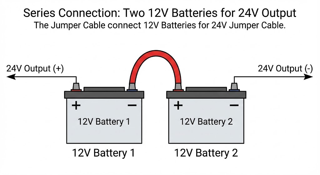
To connect batteries in series, you arrange them in a single electrical chain. The current must pass through the first battery to get to the second, and so on.

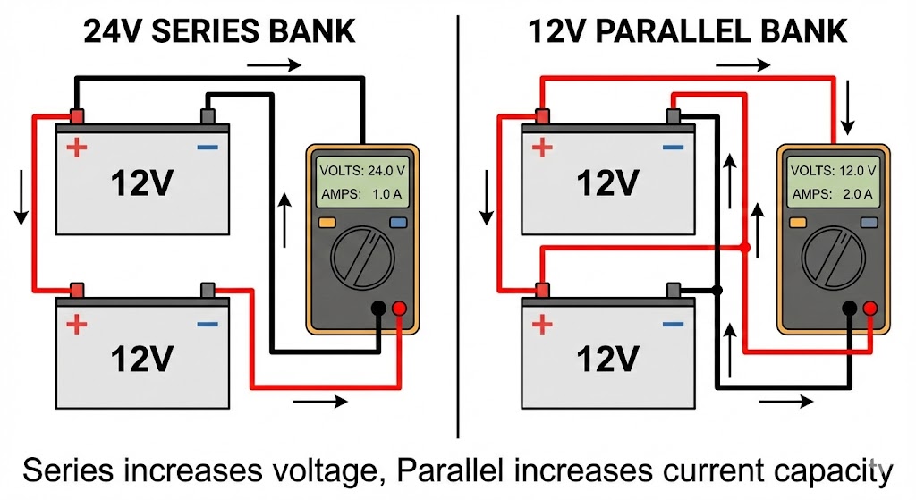
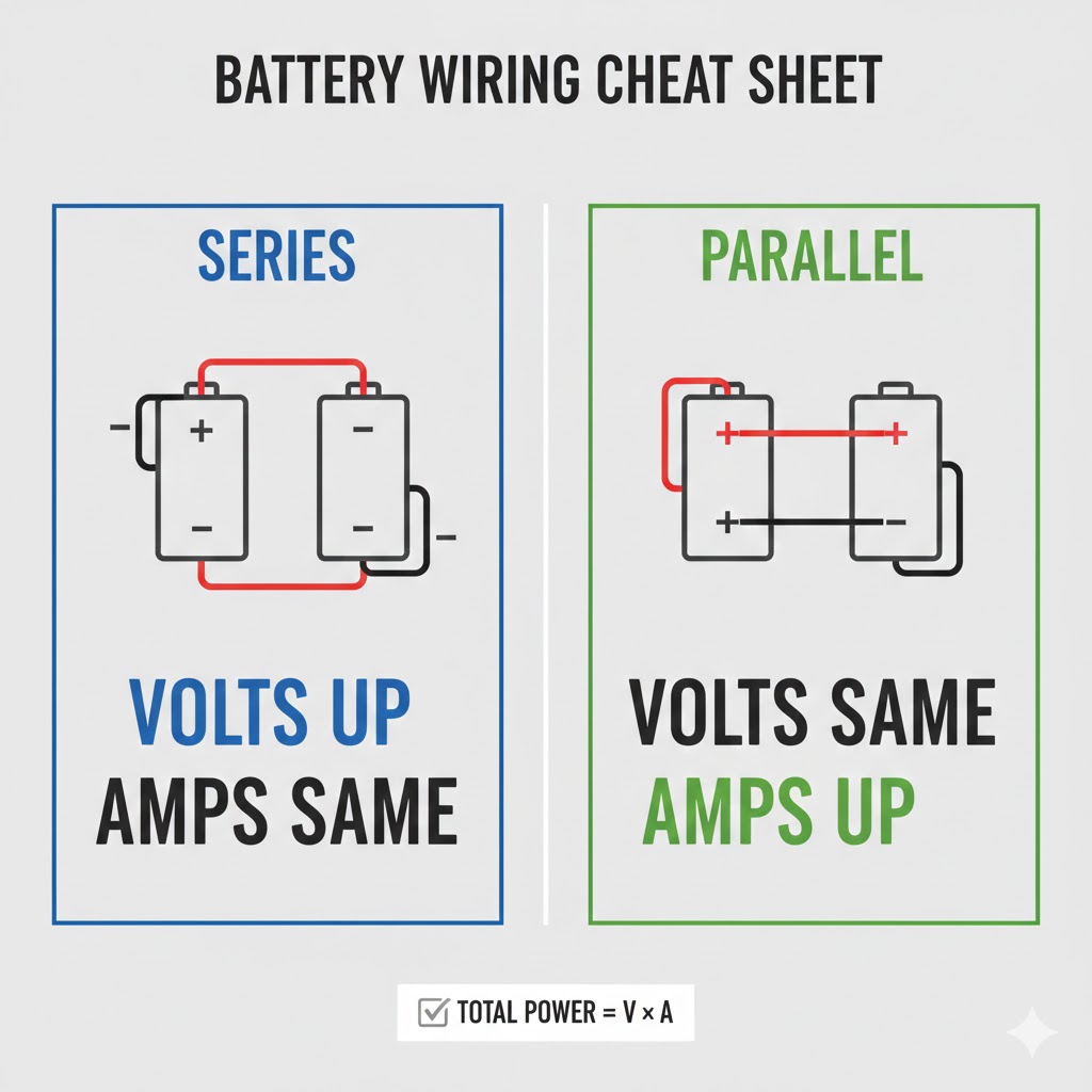
The Wiring Pattern: Connect the Negative (-) terminal of the first battery to the Positive (+) terminal of the second battery. You continue this “daisy chain” down the line.

When you are finished, you will have one remaining open Positive terminal (on the first battery) and one remaining open Negative terminal (on the last battery). These two open posts become your main system hookups.

3.2 How voltage changes in series

Think of this like stacking batteries in an old flashlight. When you drop three 1.5V batteries into the tube, they sit head-to-tail. The flashlight bulb sees 4.5V.


In a battery bank, the effect is identical. Every battery you add to the string adds its voltage to the total. This allows us to power heavy loads (like air conditioners or large inverters) more efficiently because higher voltage pushes current more easily.

3.3 What stays the same in series (capacity, Ah)

This is the most common mistake I see on the job site.

If you connect two 100Ah batteries in series, you do NOT get 200Ah. You still have 100Ah.

Why? Because the current has to flow through both batteries sequentially. It is like connecting two water hoses end-to-end. You have twice the length (pressure/voltage potential), but the hose is not any wider. You cannot flow more water per minute than the width of the hose allows.

  • Voltage: Increases

  • Amp-Hours (Capacity): Stays the same

  • Total Energy (Wh): Increases (because Energy = Volts × Amps)

3.4 Simple Formula: Total Voltage = Sum of all battery voltages

The math for series connections is straightforward.

Formula:

V_total = V₁ + V₂ + V₃ + … + Vₙ

Where V₁, V₂, V₃ are the individual battery voltages.

Examples:

Two 12V batteries in series: 12V + 12V = 24V

Three 12V batteries in series: 12V + 12V + 12V = 36V

Four 3.2V cells in series: 3.2V + 3.2V + 3.2V + 3.2V = 12.8V

Capacity stays the same:

Ah_total = Ah of a single battery (assuming all batteries have the same capacity)

If each battery is 100Ah, your series string is 100Ah regardless of how many batteries you connect.

Total energy calculation:

Wh_total = V_total × Ah_total

Two 100Ah 12V batteries in series: 24V × 100Ah = 2,400Wh

Four 50Ah 12V batteries in series: 48V × 50Ah = 2,400Wh

Different configurations can give you the same total energy at different voltage levels.

3.5 Real Examples

Here is how this looks in common real-world builds:

ConfigurationIndividual BatteryMathSystem ResultCommon Use Case
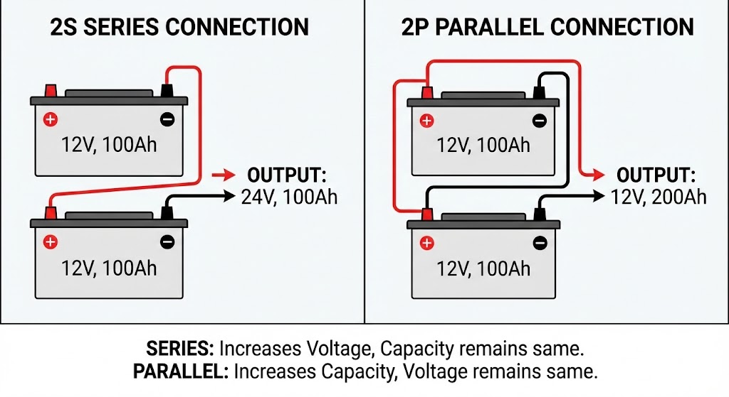
2 Series (2S)12V @ 100Ah12V + 12V24V @ 100AhTrolling motors, small solar
4 Series (4S)12V @ 200Ah12V + 12V + 12V + 12V48V @ 200AhOff-grid homes, telecom towers
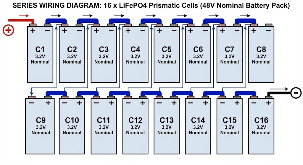
16 Series (16S)3.2V Prismatic Cell16 × 3.2V51.2VDIY Lithium Battery Packs (Server rack style)
Golf Cart (6S)6V Lead-Acid6 × 6V36VOlder golf carts

Note on “51.2V” vs “48V”: In the lithium industry, we call a 16-cell pack a “48V system” because it replaces 48V lead-acid banks, but its nominal voltage is actually 51.2V. This is normal.

Critical detail for all series connections:

Every battery in the series string must have the same amp-hour rating and be at the same state of charge when you connect them. If Battery 1 is at 100% charge and Battery 2 is at 50%, you’ll create current imbalance when you connect them. Worst case: one battery tries to charge the other through the series connection, creating a high-current event that can damage cells or trip BMS protection.

4.What Does Connecting Batteries in Parallel Mean?

While series connections are about building pressure (voltage), parallel connections are about building volume (capacity).

If you need to run your lights, fridge, and heater for three days off-grid instead of one, you don’t need higher voltage; you need a bigger fuel tank. That is what parallel wiring achieves.

4.1 Definition of parallel connection

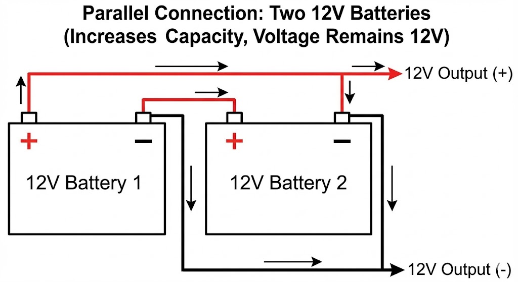
Connecting in parallel means wiring all the Positive (+) terminals together and all the Negative (-) terminals together.

Instead of the current flowing through one battery after another (like a single lane road), the current flows through all batteries simultaneously (like a multi-lane highway).

The Wiring Pattern:

  1. Connect Battery A Positive to Battery B Positive.

  2. Connect Battery A Negative to Battery B Negative.

  3. Your main system load connects to the Positive of the first battery and the Negative of the last battery (we will explain why in Section 6).

4.2 How capacity (Ah) increases in parallel

When you parallel batteries, you are essentially creating one giant battery block.

If you have two water tanks sitting at the same height (same voltage) and you connect a pipe between them, you now have twice the water. You can draw water for twice as long.

Current Splitting: This is a major advantage of parallel setups. If your inverter draws 100 Amps, and you have two batteries in parallel, each battery only has to provide 50 Amps. This reduces the strain on the individual cells, keeping them cooler and extending their life.

4.3 What stays the same in parallel (voltage)

In a parallel circuit, the voltage does not change.

If you connect ten 12V batteries in parallel, the system is still 12V. You have not increased the electrical pressure; you have only increased the reservoir of electrons available at that pressure.

Critical Warning: Never connect batteries of different voltages in parallel (e.g., a 12V connected to a 24V). The higher voltage battery will instantly dump its energy into the lower voltage one, causing massive arcing, heat, and potential fire.

4.4 Simple Formula

Total Capacity = Sum of all battery Ah ratings

The formula for parallel capacity is dead simple:

Total Capacity (Ah) = Battery 1 Ah + Battery 2 Ah + Battery 3 Ah + …

For identical batteries: Total Capacity = Number of Batteries × Individual Battery Ah

Let me show you how this works in practice.

Example 1: Identical batteries

  • 3 batteries, each rated 100Ah
  • Total capacity = 100 + 100 + 100 = 300Ah
  • Or simply: 3 × 100Ah = 300Ah

Example 2: Mixed capacities (not recommended, but here’s the math)

  • Battery A: 100Ah
  • Battery B: 80Ah
  • Battery C: 120Ah
  • Total capacity = 100 + 80 + 120 = 300Ah

That second example will work, but mixing capacities creates current sharing problems. The larger battery tries to feed the smaller ones during discharge. I strongly recommend using identical batteries whenever possible.

What about voltage? It doesn’t appear in this formula because voltage stays constant. You’re only calculating capacity.

What about C-rating or maximum discharge current? That’s a separate calculation. In parallel, your maximum safe continuous current is the sum of each battery’s rated maximum. Two batteries rated for 50A continuous can together handle 100A continuous when properly paralleled.

4.5 Real Examples

Here is how the math works out for common setups:

ConfigurationIndividual BatteryMathSystem ResultCommon Use Case
2 Parallel (2P)12V @ 100Ah100Ah + 100Ah12V @ 200AhRV house banks, camper vans
4 Parallel (4P)24V @ 50Ah50 + 50 + 50 + 5024V @ 200AhMedium solar storage
3 Parallel (3P)12V @ 300Ah300 + 300 + 30012V @ 900AhLarge marine yachts

Note: In the second example (4 × 24V), notice that the voltage (24V) stayed the same, but the capacity quadrupled.

Why 24V instead of 12V? Higher voltage systems lose less energy to wire resistance. For the same power delivery, 24V requires half the current of 12V, which means you can use smaller gauge wire and suffer fewer losses.

When you parallel four batteries, physical layout matters. Arrange them so cable lengths are as equal as possible. I’ve seen systems where the installer used a 2-foot cable to the first battery and a 10-foot cable to the last one. That creates resistance imbalance and uneven charging.

5. Series vs. Parallel: Key Differences at a Glance

When you are staring at a schematic trying to decide how to wire your bank, it helps to have a cheat sheet. This table breaks down exactly what happens to your electrical stats in each configuration.

FeatureSeries ConnectionParallel Connection
Voltage (V)Increases (Adds up)Stays the same
Capacity (Ah)Stays the sameIncreases (Adds up)
Energy (Wh)IncreasesIncreases
Max Current OutputSame as a single batteryIncreases (Sum of all batteries)
Wiring ComplexityLower (Daisy chain)Higher (Requires balancing)
Typical GoalReducing cable thickness / High PowerExtending runtime / High Capa

Engineer’s Insight on Current: Notice the “Max Current Output” row.

  • In Series: If your battery is rated for 100A max discharge, your entire system is limited to 100A.

  • In Parallel: If you have two of those batteries, your system can theoretically output 200A. However, this means your main cables and fuses must be twice as big to handle that surge.

6. When Should You Use Series Connections?

We choose series connections for one main reason: Efficiency.

As systems get larger, sticking with 12V becomes a logistical nightmare. When you are moving more than 2,000 Watts, you generally want to increase the voltage to keep the current manageable.

6.1 When your system requires higher voltage

The most obvious reason to wire in series is that your load demands it.

Many high-performance inverters, trolling motors, and industrial machines are designed for 24V or 48V inputs. You cannot feed a 48V Victron inverter with a 12V battery bank; it simply won’t turn on.

Wiring in series allows you to build a battery bank that matches the native voltage of these heavier-duty appliances

6.2 Lower current = thinner cables, less heat

This is the hidden advantage of series connections that saves you real money on wire and reduces fire risk.

Here’s the physics: Power (watts) equals voltage times current. If you need 1000W at 12V, you’re drawing about 83 amps. That same 1000W at 48V only draws about 21 amps. Higher voltage means lower current for the same power delivery.

Why this matters:

  • Lower current allows smaller gauge wire
  • Smaller wire costs less and is easier to install
  • Less current means less resistive heating in cables
  • Reduced voltage drop over distance

Real numbers from my work:

For a 3000W inverter installation with 10-foot cable runs:

System VoltageCurrent DrawMinimum Wire GaugeApprox. Cost per Foot
12V~250A4/0 AWG$8-12
24V~125A2 AWG$3-5
48V~63A4 AWG$1-2

Moving from 12V to 48V cuts your wire costs by 75% and makes installation dramatically easier. I can bend and route 4 AWG cable by hand. 4/0 AWG requires two people and special tools.

Heat generation example: I once troubleshot a 12V system where the cables got hot enough to melt the insulation. The problem wasn’t a short circuit—it was undersized wire trying to handle 200+ amps continuous. Switching to a 48V system with properly sized wire eliminated the problem entirely.

Voltage drop is another factor. At 12V, even heavy cable loses significant voltage over moderate distances. A 48V system tolerates the same resistance with one-quarter the voltage loss.

6.3 Better efficiency for inverters and motors

Your equipment prefers higher voltage, too.

  • Inverters: An inverter’s job is to boost DC battery voltage up to 120V or 230V AC. It is much easier (and more efficient) to step 48V up to 120V than it is to step 12V up to 120V. Less energy is lost in the conversion process.

     
  • DC Motors: Trolling motors and electric drive systems run more efficiently at higher voltages. They can produce more torque with less heat build-up in the windings.

6.4 Common system voltages: 24V, 36V, 48V, 72V

Different applications have settled on standard voltages based on decades of industry experience. Understanding these standards helps you design compatible systems.

12V Systems

Typical uses:

  • Small RVs and boats
  • Automotive accessories
  • Small solar setups under 500W
  • Portable power stations

Limitations: Poor choice for anything over 1000W continuous. Wire costs and efficiency losses make 12V impractical for larger systems.

24V Systems

Typical uses:

  • Medium RVs and marine vessels
  • Light commercial solar (1-2 kW)
  • Telecom backup power
  • Small electric vehicles (golf carts, mobility scooters)

Advantages: Doubles the power capacity compared to 12V with the same current. Good balance between availability of components and system efficiency.

Battery configuration: Two 12V batteries in series, or four 6V batteries in series (common in golf carts).

36V Systems

Typical uses:

  • Electric bicycles and scooters
  • Small electric boats
  • Specialized industrial equipment

Battery configuration: Three 12V batteries in series, or ten 3.6V lithium cells in series.

Note: Less common than 24V or 48V, which means fewer off-the-shelf components. I generally steer customers toward 24V or 48V unless they have specific equipment requiring 36V.

48V Systems

Typical uses:

  • Residential off-grid and grid-tie solar (most popular choice)
  • Large RVs and yachts
  • Telecom central offices
  • Medium electric vehicles
  • Data center backup power

Advantages:

  • Sweet spot for efficiency and safety
  • Widely supported by inverters and charge controllers
  • Still considered “low voltage” (under 50V) for safety regulations in most jurisdictions
  • Excellent wire gauge economy for systems up to 10kW

Battery configuration: Four 12V batteries in series, or sixteen 3.2V LiFePO4 cells in series.

My recommendation: For any off-grid home over 3kW, start with 48V. The component availability and efficiency gains are worth it.

72V Systems

Typical uses:

  • Larger electric vehicles (neighborhood electric vehicles, small trucks)
  • High-power e-bikes and motorcycles
  • Industrial material handling equipment
  • Some commercial solar installations

Battery configuration: Six 12V batteries in series, or twenty-four 3.2V LiFePO4 cells in series.

Safety note: 72V exceeds the typical 50V “low voltage” threshold in many electrical codes. This may require additional safety equipment and qualified electrician installation depending on your jurisdiction.

Higher voltages (96V+)

Typical uses:

  • Grid-tie solar inverters (96V, 120V, 240V, or higher)
  • Electric vehicles (200-800V)
  • Large commercial and industrial systems

Critical warning: Systems over 50V present serious shock hazards. These require professional design, proper safety equipment, and strict adherence to electrical codes. I don’t recommend DIY installations above 48V unless you have formal electrical training.

Choosing your system voltage:

Based on 15 years of installations, here’s my rule of thumb:

  • Under 500W: 12V is fine
  • 500W to 2kW: Consider 24V
  • 2kW to 10kW: Use 48V
  • Over 10kW: 48V minimum, consider higher voltages with professional design

Your equipment voltage requirements override these guidelines. Always match your battery bank voltage to your inverter, charge controller, and load requirements first.

7. When Should You Use Parallel Connections?

We choose parallel connections when we need endurance. If your voltage is already fixed by your equipment—say, you have a 12V RV system—but you’re tired of the lights going dim after three hours, you wire in parallel.

Parallel wiring increases your “fuel tank” (Capacity) without changing the “pressure” (Voltage).

7.1 When longer runtime is needed

Parallel connections are your primary tool for extending how long your system can run between charges. This is the most common reason I recommend parallel configurations to customers.

The fundamental principle: Adding batteries in parallel multiplies your available amp-hours while maintaining the same voltage. More amp-hours means longer runtime under the same load.

Simple runtime calculation:

Runtime (hours) = Total Capacity (Ah) ÷ Load Current (A)

Real example: A marine refrigerator draws 4 amps at 12V. With one 100Ah battery, you get about 25 hours of runtime (accounting for the 80% depth of discharge limit on lead-acid). Parallel a second 100Ah battery and you double that to 50 hours.

Common applications where runtime matters:

  • RV house batteries: Running lights, fans, water pumps, and appliances for multi-day camping trips without shore power or generator use
  • Off-grid solar systems: Providing power through cloudy days or winter months when solar production is limited
  • Marine systems: Operating navigation equipment, communication radios, and living accommodations during extended passages
  • Backup power: Keeping critical loads running during extended utility outages
  • Remote monitoring stations: Weather stations, security cameras, and sensors that must operate continuously in locations without grid power

Why not just buy bigger batteries? Sometimes larger single batteries aren’t available, or parallel smaller units gives you better pricing. Four 100Ah batteries often cost less than one 400Ah battery, plus you gain redundancy—if one fails, you still have 75% capacity available.

7.2 Keeping voltage compatible with existing equipment

In many scenarios, you are stuck with a specific voltage.

  • RVs and Vans: Most camper vans come pre-wired for 12V. All the lights, water pumps, and fans are 12V. If you switched to series (24V), you would blow out every bulb and motor in the vehicle.

  • Alternator Charging: Your vehicle’s alternator puts out ~14V. It can charge a 12V parallel bank directly. If you built a 24V series bank, you would need an expensive DC-DC converter to charge it.

In these cases, parallel is your only option. You increase capacity while keeping the system compatible with the hardware you already own.

7.3 Increasing current supply for large loads

This is a technical advantage often overlooked. Parallel banks can deliver massive surge currents.

Every battery has a maximum discharge rate (C-rating). For a standard 100Ah Lithium battery, the BMS might limit output to 100 Amps.


If you try to start a large microwave that surges to 150 Amps, a single battery will shut down (BMS Over-Current Protection).

The Parallel Solution:

  • 1 Battery: Max output = 100A (Microwave fails).

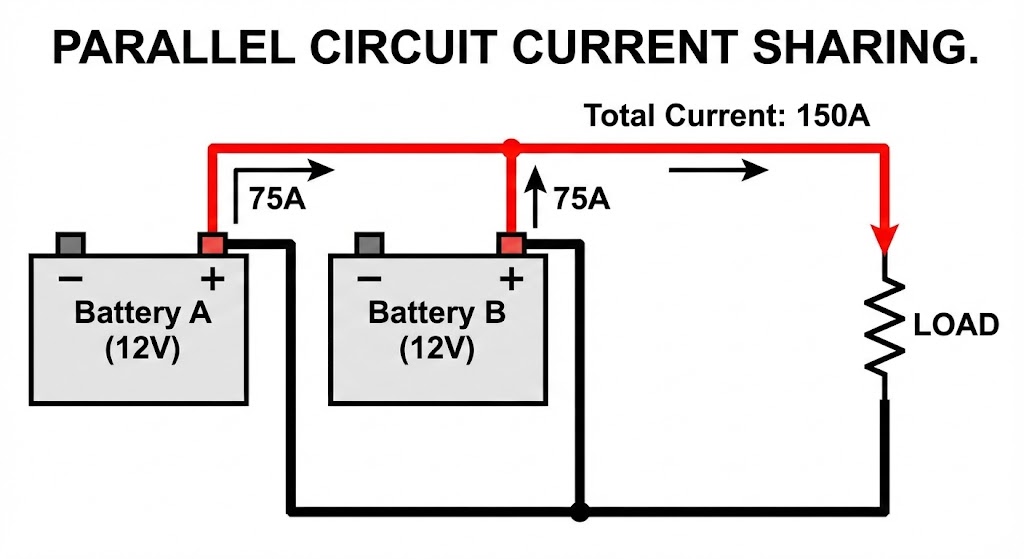
  • 2 Batteries in Parallel: Max output = 200A. The load is shared. Each battery only contributes 75A, which is well within the safe zone. The microwave runs, and the batteries stay cool.

Warning: While the batteries can now handle 200A, your main cables must be upgraded to handle that combined current.

Typical battery current ratings:

Battery TypeContinuous CurrentPeak Current (10 sec)
100Ah AGM50-70A (0.5-0.7C)150-200A
100Ah Flooded Lead-Acid20-50A (0.2-0.5C)100-150A
100Ah LiFePO4100-200A (1-2C)200-400A
 

8. Series-Parallel Battery Banks (Advanced Setup)

Sometimes, you need it all: high voltage for inverter efficiency and high capacity for long runtime. You cannot get there with simple series or parallel strings alone. You need to combine them.

This is the standard architecture for large-scale solar arrays, electric boat propulsion, and off-grid home backups. It sounds complex, but it is just building blocks.

8.1 What is a series-parallel configuration?

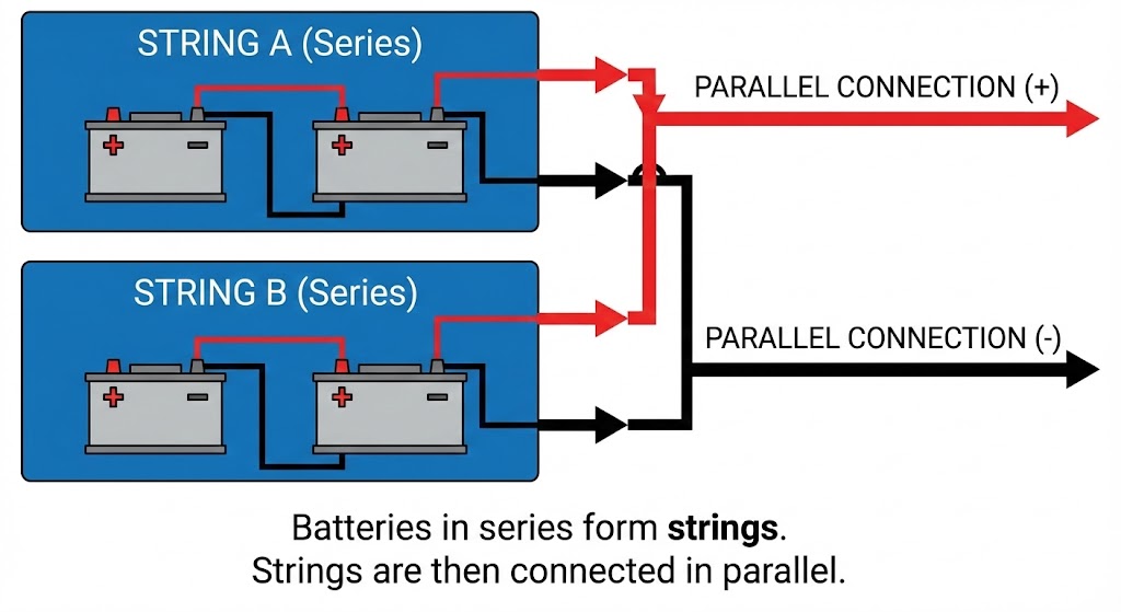
A series-parallel bank is exactly what it sounds like: you connect batteries in series to hit your voltage target, and then connect those strings in parallel to hit your capacity target.

Think of it as creating “Super Batteries.”

  1. Step 1 (Series): You connect smaller batteries in series to create a “String” that meets your system voltage (e.g., 24V or 48V).

  2. Step 2 (Parallel): You treat those Strings as if they were single batteries and connect them in parallel to increase amp-hours.

Why not just buy a bigger battery? Sometimes you can’t. If you need a 48V 800Ah bank, you generally cannot buy a single 3,000lb battery block. You have to build it out of manageable 12V or 2V cells.

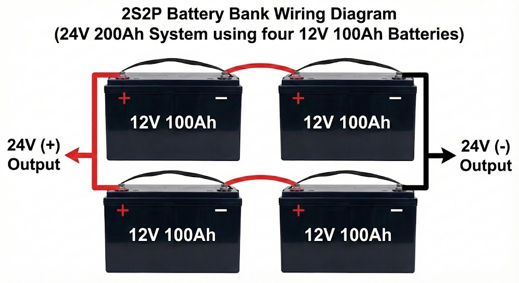
8.2 Example: 4 batteries making 24V 200Ah

Let’s say you have four 12V 100Ah batteries. You want a 24V system.

The Wrong Way: If you put all four in series, you get 48V 100Ah (Voltage too high). If you put all four in parallel, you get 12V 400Ah (Voltage too low).

The Series-Parallel Way (2S2P):

  1. Create String A: Connect Battery 1 and Battery 2 in series.

    • Result: One 24V 100Ah string.

  2. Create String B: Connect Battery 3 and Battery 4 in series.

    • Result: One 24V 100Ah string.

  3. Parallel the Strings: Connect the positive of String A to the positive of String B. Do the same for the negatives.

    • Final Result: 24V 200Ah.

You now have a system that can handle 24V loads but runs twice as long as a single string.

8.3 Why symmetry in wiring is critical

In a series-parallel bank, physics will punish you if you are lazy.

Electricity follows the path of least resistance. If String A has a slightly shorter cable or a slightly cleaner crimp than String B, String A will have lower resistance.

The Consequence: Current will rush into String A faster than String B.

  • During Charging: String A gets overcharged and hot. String B never gets full.

  • During Discharging: String A does 70% of the work and dies early. String B sits lazy.

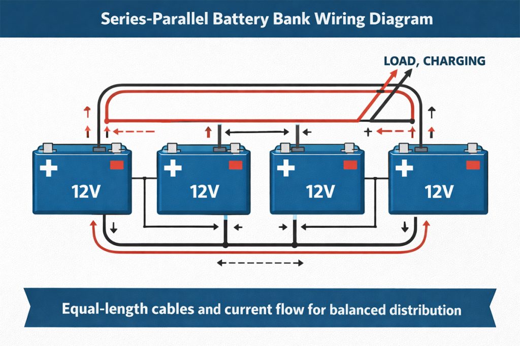
The “Tic-Tac-Toe” Rule: To prevent this, the wiring must be perfectly symmetrical.

  • Cable Length: The cables connecting String A must be the exact same length (down to the inch) as the cables connecting String B.

  • Diagonal Take-off: You must connect your main positive load cable to String A and your main negative load cable to String B. This forces the electricity to travel the same total distance through wire regardless of which string it flows through.

If you wire a large bank unsymmetrically, you will kill half your batteries within a year or two. I have seen $10,000 banks destroyed because one cable was 6 inches shorter than the other.

9. Critical Safety Rules (Most Guides Skip These)

Most online tutorials show you how to connect the wires, but they rarely tell you what you are connecting. This is where the expensive mistakes happen.

A battery bank is a team. If the team members aren’t identical, they don’t work together—they fight. And in electrical engineering, “fighting” means heat, reduced lifespan, and potential failure.

9.1 Never mix different battery types or chemistries

This is the #1 rule I hammer into every customer, yet I still see it violated constantly. Mixing battery chemistries in the same bank is asking for fire, explosion, or rapid battery failure.

Why different chemistries don’t play together:

Each battery chemistry has fundamentally different electrical characteristics:

ChemistryNominal VoltageCharge VoltageInternal ResistanceSelf-Discharge
Flooded Lead-Acid12V (6 cells × 2.0V)14.4-14.8VMedium-High5-15% per month
AGM Lead-Acid12V (6 cells × 2.0V)14.4-14.7VLow-Medium1-3% per month
Gel Lead-Acid12V (6 cells × 2.0V)14.0-14.2VMedium1-3% per month
LiFePO412.8V (4 cells × 3.2V)14.4-14.6VVery Low<1% per month

This is the cardinal sin of battery storage. You cannot mix Lead-Acid (AGM/Gel/Flooded) with Lithium (LiFePO4) in the same bank.

The Voltage Conflict:

  • Lead-Acid: Rests at ~12.7V when full.

  • LiFePO4: Rests at ~13.3V – 13.6V when full.

If you connect them, the higher-voltage Lithium battery will immediately try to “charge” the Lead-Acid battery. It will drain itself constantly, 24/7, trying to push the Lead-Acid voltage up. You end up with a dead Lithium battery and a cooked Lead-Acid battery that has been held at too high a voltage for too long.

Charge Profile Mismatch: Chargers use specific curves (Bulk, Absorption, Float). A curve designed for AGM will not charge Lithium correctly, and a Lithium curve can boil an AGM battery. You can’t satisfy both.

9.2 Do not mix old and new batteries

I often see customers buy two batteries, run them for three years, and then decide they need more capacity. They buy two new batteries of the exact same brand and model and bolt them in.

This is a mistake.

Batteries degrade chemically over time.

  • The Old Battery: Has higher internal resistance and lower capacity (maybe 80Ah left of the original 100Ah).

  • The New Battery: Has low resistance and full 100Ah capacity.

When you connect them, the new battery will do 80% of the work because electricity follows the path of least resistance. It will cycle harder and die faster, effectively aging down to the level of your old batteries within months. You degrade the new investment immediately.

9.3 Match voltage, capacity, and internal resistance

Ideally, every battery in your bank should come from the same manufacturing batch.

Why matching matters:

  • Voltage: If voltages differ, current flows from high to low instantly (and dangerously).

  • Capacity: In a series string, the smallest battery dictates the limit. If you have a 100Ah and a 50Ah in series, your system is 50Ah. Once the small one is empty, the voltage crashes. If you keep drawing power, you will “reverse polarity” the small battery, destroying it.

  • Internal Resistance: This determines how fast a battery can release energy. Mismatched resistance leads to “current hogging,” where one battery runs hot while the other sits idle.

9.4 Balance batteries before connecting (especially lithium)

With Lead-Acid, you can usually just hook them up and let the charger sort it out. With Lithium, you cannot.

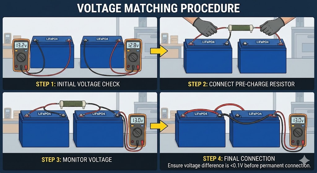
Lithium batteries have extremely low internal resistance. If you connect a fully charged Lithium battery (14.6V) to a half-charged one (12.8V), there is almost nothing to stop the current flow.

The “Inrush” Danger: The current will rush from the full battery to the empty one instantly. We are talking hundreds, potentially thousands of Amps in a millisecond.

  • The Result: Massive sparks, melted terminal posts, and the BMS (Battery Management System) will instantly trip into protection mode (or burn out).

The Correct Procedure:

  1. Charge each battery individually to 100% using a 12V charger.

  2. Let them rest for a few hours.

  3. Check voltage with a multimeter. They should be within 0.05V of each other.

  4. Then connect them.

9.5 Each parallel string needs its own fuse or breaker

This is a safety standard (ABYC E-11) that many DIYers miss.

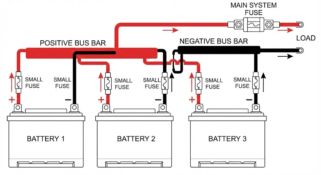
If you have a large bank with 3 or more parallel strings, a main fuse on the final output is not enough.

The Failure Scenario: Imagine you have 4 batteries in parallel. Battery #1 develops an internal short circuit.

  • Batteries #2, #3, and #4 see a path to ground through Battery #1.

  • They all dump their energy into Battery #1 simultaneously.

  • The current does not go through the main system fuse; it circulates internally between the batteries.

Without individual fuses on each battery (or string), Battery #1 becomes a heater that can reach thermal runaway temperatures in seconds.

10. Wiring Best Practices for Parallel Banks (Very Important)

Parallel banks are deceptively simple. You just match the plusses and minuses, right? Wrong.

The goal in a parallel bank is perfect balance. We need every electron to face the exact same amount of resistance, no matter which battery it comes from. If one battery is easier to access electrically than the others, it will do all the heavy lifting and die prematurely.

We achieve this balance through geometry and physics, not hope.

10.1 Use Equal Cable Lengths

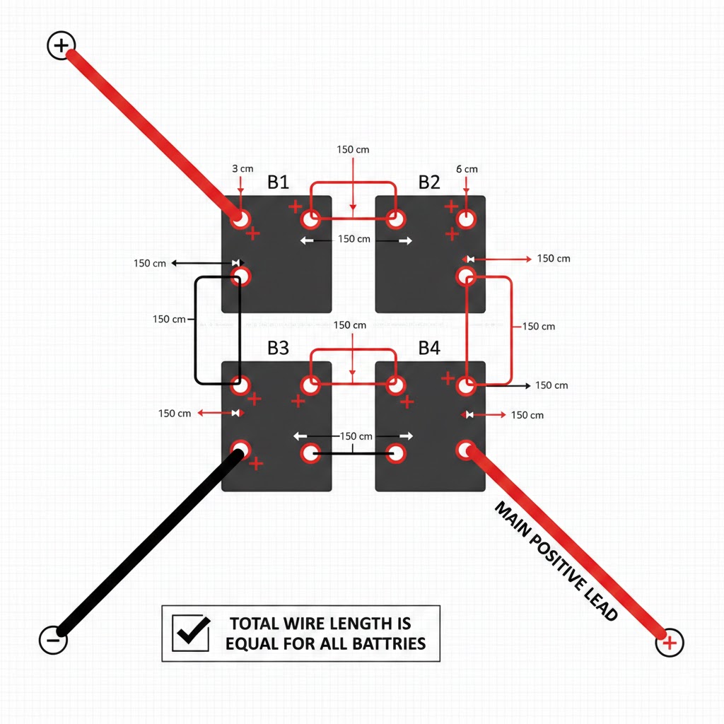
This is the golden rule of parallel wiring: Every interconnect cable must be the exact same length.

I don’t mean “close enough.” I mean cut to the millimeter. If you are connecting four batteries in parallel, the jumper cables between Battery A and B must be identical to the ones between C and D.

The Physics: Wire has resistance. Longer wire = more resistance. If the cable to Battery #1 is 12 inches long and the cable to Battery #2 is 18 inches long, Battery #1 offers a path of lower resistance. Current will flood out of Battery #1 first. It will cycle deeper, heat up more, and fail years before Battery

10.2 Use Busbars Instead of "Daisy Chain" Wiring

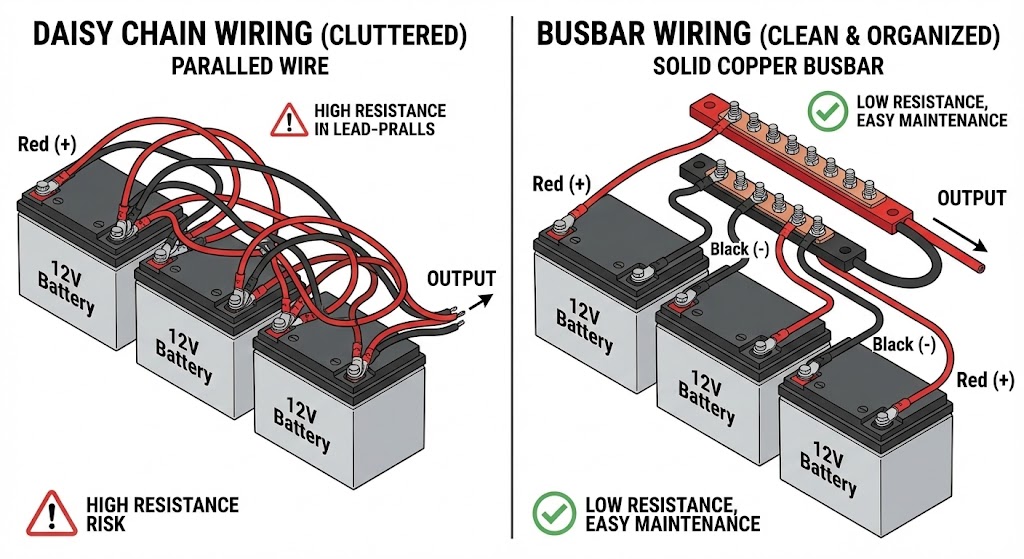
The “Daisy Chain” method involves stacking multiple lugs onto a single battery post to jump to the next one.

  • Why it fails: Every time you stack a lug, you add contact resistance. By the time you get to the fourth battery in the chain, the current has to push through three sets of connections to get out. The voltage drop becomes significant.

The Busbar Solution: A busbar is a heavy chunk of conductive copper. Instead of connecting batteries to each other, you connect every battery individually to the busbar.

 
  • The busbar becomes the “common point.”

  • Every battery has a direct, dedicated lane to the highway.

  • It looks cleaner, is easier to troubleshoot, and ensures equal resistance.

10.3 Take System Positive and Negative from Opposite Ends

If you must daisy chain (because you don’t have space for busbars), you must use the “Diagonal” or “Cross-Corner” method.

The Mistake: Connecting your main Positive and main Negative cables to the same battery (usually the first one).

  • Result: Battery #1 takes the full hit. Battery #4 is far away at the end of the line. The resistance of the jumper cables means Battery #4 barely participates.

The Fix (Diagonal Take-off):

  1. Connect your Main Positive cable to Battery #1.

  2. Connect your Main Negative cable to Battery #4 (the last one).

Why this works: Trace the path of the electricity.

  • From Battery #1: The current travels through 0 jumpers on the positive side, but 3 jumpers on the negative side to get out. Total jumpers: 3.

  • From Battery #4: The current travels through 3 jumpers on the positive side, but 0 jumpers on the negative side. Total jumpers: 3.

Every battery now pushes through the exact same total length of wire. The load is shared perfectly.

10.4 Why Poor Wiring Causes Uneven Battery Aging

When resistance is unbalanced, you get “Current Hogging.”

Let’s say Battery A takes 40 Amps of the load, while Battery B (due to poor wiring) only takes 10 Amps.

  • Battery A is cycling 4x harder. It will hit its cycle life limit (say, 3,000 cycles) much faster.

  • Once Battery A fails, the entire 50 Amp load shifts to Battery B.

  • Battery B, which isn’t used to the heat, gets overworked and fails shortly after.

You end up replacing the entire bank because of a few feet of poorly planned wire. Proper wiring ensures they all wear down at the same slow rate, maximizing your ROI.

11. Lithium Battery (LiFePO₄) Special Considerations

Lithium Iron Phosphate (LiFePO₄) batteries are not just blocks of lead; they are smart devices with onboard computers called Battery Management Systems (BMS). This adds a layer of complexity that didn’t exist with old-school batteries.

If you treat a lithium battery exactly like a lead-acid battery, you will eventually trip a sensor, blow a MOSFET, or void your warranty.

11.1 BMS Limits for Series and Parallel Connections

Inside every lithium battery is a circuit board (BMS) that controls power flow. This board has hard physical limits.

  • In Parallel (Current Limits): If you have a 100Ah battery with a BMS rated for 100A continuous discharge, putting two in parallel theoretically gives you 200A capacity. However, you rely on perfect current sharing. If one battery has slightly lower resistance, it might try to take 120A while the other takes 80A. The first battery’s BMS will trip, dumping the full 200A load onto the second battery, which then trips instantly. You end up with a “cascading failure” where the whole bank shuts down.

  • In Series (Voltage Limits): The MOSFETs (switches) inside a 12V BMS are typically rated for relatively low voltages (often around 30V or 60V). If you connect four 12V batteries in series to make 48V, the total system voltage is high. If a BMS trips, it has to withstand electrical stress it wasn’t necessarily designed for.

11.2 Why BMS Cutoff Can Affect Series Strings

This is a specific risk called “The Open Circuit Voltage Spike.”

Imagine you have four 12V batteries in series running a heavy load. Suddenly, Battery #3 detects a cell voltage that is too low and its BMS cuts power.

  1. Instant Blackout: Because it is a series chain, the circuit is broken. Power to your house/boat stops instantly.

  2. The Voltage Spike: When current stops abruptly, magnetic fields in the wires collapse, creating a voltage spike (inductance).

  3. The “Hot Switch” Scenario: The open BMS switch on Battery #3 now has the potential of the other three batteries pressing against it. If the components aren’t rated for that combined voltage, the BMS in Battery #3 will fry, permanently destroying the battery.

The Fix: This is why you must check the datasheet. If a manufacturer says “Max 4 Series,” they have verified their components can survive this event. If you try to do 5 Series, you are gambling with $4,000 worth of batteries.

11.3 Pre-charge and Voltage Matching Before Paralleling

We touched on this in safety, but for Lithium, it is non-negotiable because of the flat voltage curve.

A LiFePO₄ battery stays at roughly 13.2V – 13.3V for most of its discharge cycle.

  • The Danger: A battery at 13.4V might be 90% full, while a battery at 12.9V is 20% full. The voltage difference looks small (0.5V), but the energy difference is massive.

  • The Surge: If you connect these two, the full battery sees the empty one as a short circuit. It dumps current fast. Because lithium has very low internal resistance, this current can exceed the BMS short-circuit rating, causing it to shut down immediately (or weld the contactor shut).

Procedure: Never parallel lithium batteries straight out of the box. Charge each one individually to 100% (until the charger stops) first. This ensures they are all at the exact same saturation point.

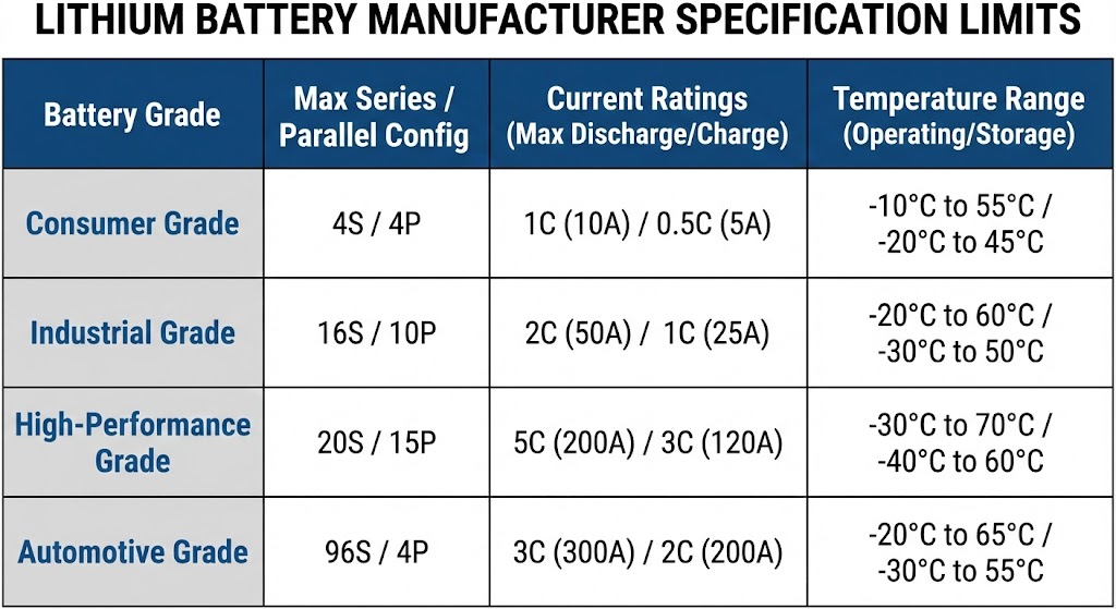
11.4 Manufacturer Limits You Must Follow

You cannot just stack batteries infinitely like Lego bricks. Manufacturers set strict limits for a reason: Timing and Communication.

If a spec sheet says “Max 4P” (4 Parallel) or “Max 2S” (2 Series), follow it.

Why the limit exists:

  • Balancing Issues: In large series strings (e.g., 4S), the internal cell balancers (which are usually very weak/slow) cannot keep up with the drift across the whole bank. The pack will become unbalanced quickly.

  • Inrush Current: In large parallel banks (e.g., 10P), the combined inrush current when turning on an inverter can be thousands of amps—enough to damage the master switch or fuse.

Pro Tip: If you need a larger bank than the “Max Series/Parallel” rating allows, you generally need to switch to a different battery model (like a native 48V server rack battery) rather than daisy-chaining dozens of small 12V blocks.

12. Protection Design: Fuses and Breakers

When you work with batteries day in and day out, you learn one rule very quickly: Energy wants to get out.

If you give that energy an unintentional path—like a dropped wrench or a chafed wire—it will take it. Without protection, a battery bank doesn’t just stop working; it melts cables, welds metal, and starts fires.

This section covers how to keep that energy contained using fuses and circuit breakers. This isn’t just code compliance; it’s about keeping your rig and your face intact.

12.1 Why every battery string needs protection

Many new integrators think the Battery Management System (BMS) is their safety net. This is a dangerous assumption.

A BMS uses MOSFETs (solid-state switches) to cut power. While they are fast, they have limits. In a massive short circuit event, the surge current can be high enough to weld these MOSFETs into the “ON” position. If that happens, your BMS is effectively bypassed, and you have zero protection.

You need a physical disconnect—a fuse or a breaker—that physically separates the circuit when things go wrong.

The “Weakest Link” Rule In any electrical circuit, if there is a short, the weakest point will burn up first to break the connection.

  • With a fuse: The fuse blows safely inside a fire-resistant housing.

  • Without a fuse: Your power cable becomes the fuse. The insulation melts, the copper glows red hot, and you have a fire.

Key functions of protection:

  • Cable Protection: Prevents the wire from carrying more current than it is rated for.

  • Catastrophic Fail-safe: Acts as the last line of defense if the BMS fails or an external short occurs.

  • Service Disconnect: Breakers allow you to manually cut power for maintenance.

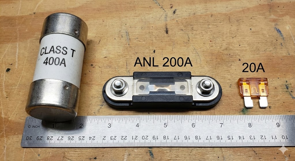
Engineer’s Note on AIC: When buying fuses, look at the AIC (Ampere Interrupting Capacity). A standard car fuse might handle 30 amps, but it can’t stop a 10,000-amp spike from a lithium bank. It will just arc over. For lithium banks, you generally need Class T or ANL fuses with high interrupt ratings.

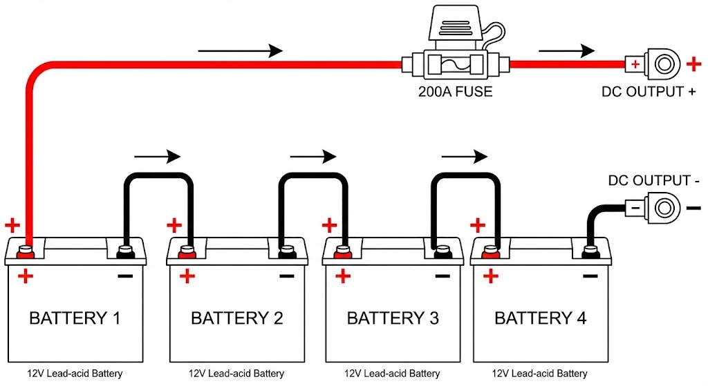
12.2 Where to place fuses in series setups

In a series connection, voltage adds up, but the current flows in a single loop. If you break the loop anywhere, current stops. However, standard practice dictates specific placement for safety and code compliance.

The Golden Rule: Place the fuse or breaker as close to the battery positive terminal as physically possible.

Why close to the source? The fuse only protects the wire downstream from it. If you place the fuse 4 feet away from the battery, those 4 feet of cable are unprotected. If a short happens in that section, there is nothing to stop the current.

Series Configuration Checklist:

  • Main Fuse: Install on the main positive cable leaving the battery bank.

  • Distance: Aim for within 7 inches (18 cm) of the terminal if possible (ABYC standard).

  • Voltage Rating: This is critical in series. If you have four 12V batteries in series (48V total), your fuse/breaker must be rated for at least 58V DC. Never use AC breakers for DC battery banks; they cannot extinguish the electrical arc created by DC power.

12.3 Where to place fuses in parallel setups

Parallel connections are trickier. When you connect batteries in parallel to increase capacity (Amp-hours), you create a scenario where batteries can discharge into each other.

If you have four batteries in parallel and one develops an internal short, the other three batteries will dump their entire energy payload into the bad battery. A single main fuse on the output cable will not see this current and will not blow.

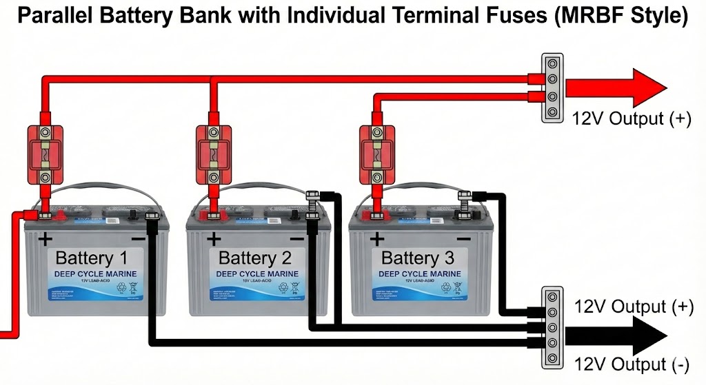
The Solution: Individual Battery Fusing For high-capacity banks, you should fuse every battery individually before they connect to the main busbar.

Recommended Setup:

  1. Terminal Fuses: Use a terminal-mounted fuse (like an MRBF) on the positive post of each battery.

  2. Main Fuse: Use a large Class T or ANL fuse on the main output line to protect the system cabling.

Why this matters:

  • Internal Shorts: If Battery A shorts internally, its specific fuse blows, isolating it. Batteries B, C, and D are safe, and the system keeps running.

  • Cable Shorts: If a specific jumper cable shorts out, only that battery’s fuse blows.

If you skip individual fuses, you must ensure your interconnect cables can handle the combined short-circuit current of the entire bank, which is usually impractical.

12.4 Common failure scenarios and how protection prevents damage

It helps to visualize exactly what we are protecting against. These aren’t theoretical; I have seen every one of these happen in the field.

Failure ScenarioWhat Happens Without ProtectionHow Protection Helps

The “Wrench Drop”


(Tool falls across terminals)

The tool welds to the posts instantly. The battery dumps thousands of amps. The battery casing may rupture or explode due to thermal runaway.The fuse blows instantly (usually in milliseconds). The arc is extinguished inside the fuse body. The battery survives.

Cable Rub / Chafing


(Vibration wears through insulation)

The positive cable touches the metal chassis (ground). The cable turns into a heating element, igniting nearby carpet, wood, or insulation.As soon as the copper touches the chassis, current spikes. The fuse blows before the wire insulation can catch fire.

BMS MOSFET Failure


(Solid-state switch stuck “ON”)

You cannot turn off the battery. If a load shorts out downstream, the BMS cannot stop it. The system runs until destruction.The fuse acts as a physical fail-safe. It doesn’t care about software or MOSFET states; it melts physically to cut power.
Inverter Capacitor ShortA failing component inside your inverter draws massive current. It can destroy the battery cells by over-discharging them rapidly.The breaker trips or fuse blows, isolating the expensive battery bank from the faulty, cheaper inverter.

A Note on “Nuisance Tripping”

Sometimes a fuse blows or breaker trips when nothing is wrong. This usually happens during inrush current—the split-second spike when you turn on a large inverter.

  • The Fix: Do not just upsize the fuse to a dangerous level. Check your device specs. You may need a “Slow Blow” or “Time Delay” fuse that tolerates a 0.5-second spike but still protects against a sustained short.

13. How to Choose: Series or Parallel? (Decision Framework)

You now know the physics, the safety rules, and the wiring diagrams. But when you are standing in front of an empty battery bay with a credit card in hand, what do you actually buy?

Designing a battery bank isn’t guesswork. It follows a logical order of operations. I use this exact four-step framework when designing systems for clients. It prevents the common mistake of buying batteries first and figuring out how to wire them second.

13.1 Step 1 — Determine system voltage requirement

Start with the load, not the battery. Your inverter or primary motor dictates the system voltage.

The Power Rule: Look at the maximum continuous power you expect to draw.

  • Under 2,000 Watts: 12V is acceptable. (Common for RVs, vans, small boats).

  • 2,000 – 4,000 Watts: 24V is highly recommended. 12V cabling becomes too thick and expensive here.

  • Over 4,000 Watts: 48V is mandatory. You need the efficiency and safety of high voltage.

Constraint Check: Do you have existing equipment you cannot replace?

  • If your alternator, lights, and water pump are already 12V, you are likely stuck with 12V unless you want to rewire the whole vehicle.

  • If this is a fresh build (like an off-grid cabin), always choose the highest voltage practical (usually 48V).

13.2 Step 2 — Calculate energy needed (Wh)

Stop thinking in Amp-hours for a moment. Amp-hours change based on voltage. Watt-hours (Wh) are universal.

Calculate how much energy you need to survive between charges.

The Calculation:

  1. List your appliances.

  2. Multiply their Wattage by the hours you run them.

  3. Sum it up.

Example:

  • Laptop (60W) × 5 hours = 300 Wh

  • Fridge (50W average) × 24 hours = 1,200 Wh

  • Lights (20W) × 4 hours = 80 Wh

  • Total Needed: 1,580 Wh per day.

Engineer’s Safety Margin: Batteries shouldn’t be drained to 0%. Multiply your total by 1.2 for Lithium (to keep 20% reserve) or 2.0 for Lead-Acid (to keep 50% reserve).

  • Target for Lithium: 1,580 × 1.2 = ~1,900 Wh.

13.3 Step 3 — Choose battery capacity

Now pick a “building block”—a single battery available on the market. Common options:

  • 12V 100Ah (1,280 Wh) – The standard block.

  • 12V 200Ah (2,560 Wh) – Good for dense packing.

  • 24V 50Ah (1,280 Wh) – Good for 24V native systems.

Let’s stick with the standard 12V 100Ah (1,280 Wh) block for our example.

13.4 Step 4 — Decide number of parallel strings

Now we do the math to fit the blocks into the requirements.

Scenario A: You need 12V and ~1,900 Wh

  • Target Voltage: 12V (Matches battery voltage).

  • Target Energy: 1,900 Wh.

  • One Battery: 1,280 Wh. (Not enough).

  • Two Batteries: 2,560 Wh. (Plenty).

  • Configuration: Since the voltage matches (12V), you connect them in Parallel.

    • Result: 2P (Parallel) System.

Scenario B: You need 24V and ~3,000 Wh

  • Target Voltage: 24V.

  • Target Energy: 3,000 Wh.

  • One Battery (12V 100Ah): 1,280 Wh.

  • Total Batteries Needed: $3,000 / 1,280 = 2.3$ (Round up to 3 or 4). Let’s use 4 for symmetry.

  • Configuration:

    1. Connect pairs in Series to hit 24V (12V + 12V).

    2. Connect those pairs in Parallel to add capacity.

    • Result: 2S2P (Series-Parallel) System.

The “Keep It Simple” Limit:

If your math tells you that you need 8 parallel strings (8P) to hit your capacity, stop. Managing 8 parallel strings is a wiring nightmare.

  • Better Move: Switch to a larger capacity battery (e.g., 200Ah or 300Ah blocks) or a higher voltage to reduce the number of physical units. Aim for the simplest layout possible.

14. Common Mistakes to Avoid

We have covered the “How-To,” but sometimes it is just as important to study the “How-Not-To.” I have been called out to fix hundreds of systems that failed prematurely. 90% of the time, the equipment was fine; the installation was the problem.

Here are the four most common ways I see people destroy expensive battery banks.

14.1 Uneven cable resistance

We discussed cable length in the parallel section, but resistance isn’t just about length. It is about termination quality.

You can cut two cables to the exact same length, but if one has a professional hydraulic crimp and the other has a loose “hammer crimp,” they have different resistance.

The “Hidden” Failure:

  • Scenario: You build a perfect parallel bank, but one battery has a slightly loose nut on the terminal.

  • The Result: High resistance at that loose connection prevents that battery from charging fully. It sits at 80% while the others hit 100%. Over months, this “lazy” battery sulphates (lead-acid) or becomes unbalanced (lithium), eventually dragging the whole bank down.

The Fix: Use a torque wrench. “Hand tight” is not a measurement. Check the manufacturer’s torque spec (usually 8–12 Nm for M8 terminals) and verify every single connection.

14.2 Connecting batteries at different charge levels

I see this often with impatient installers. You buy four batteries, they arrive in the mail, and you immediately bolt them together.

Why this is dangerous: Batteries sit on shelves for months. Battery A might be at 12.9V, while Battery B is at 12.4V.

  • The “Instant Equalization”: As soon as you connect them in parallel, physics demands they equalize. Battery A dumps current into Battery B.

  • The Damage: Without a resistor or load in between, this current is uncontrolled. I have seen it melt the tips of screwdrivers. Even if nothing melts, you have just shocked the internal chemistry and potentially fused the contactor inside a lithium BMS.

The Fix: Always charge every battery individually to 100% before you ever let them touch each other.

14.3 Ignoring temperature differences

Batteries are chemical reactors. They produce heat when working.

The “Hot Sandwich” Mistake: Installers often jam batteries tightly together to save space, touching side-by-side.

  • The Problem: The batteries in the middle of the pack have nowhere to vent their heat. They are heated by their own operation and the batteries next to them.

  • The Consequence: For every 10°C (18°F) rise in temperature above 25°C, a lead-acid battery’s life is cut in half. The middle batteries will cook and fail years before the outer ones.

The Fix: Leave an air gap. A standard rule of thumb is at least 0.5 to 1 inch (12–25 mm) of air space between every battery block. If they are in a box, ensure active ventilation (fans) or passive vents.

14.4 Overloading a single string

This happens in Series-Parallel banks (e.g., two strings of 24V).

The Scenario: You have two strings of batteries. String A and String B. One day, a fuse blows on String A, or you disconnect it for maintenance.

  • The Mistake: You forget to reduce your load. You turn on the microwave or air conditioner.

  • The Result: The entire load of the house—normally shared by two strings—now crashes onto String B alone. This creates massive current (often 2x the normal rate). This can instantly trip the BMS, blow the main fuse, or overheat the cables of String B.

The Fix: If you have a multi-string bank, always remember: If one string goes down, your capacity and your maximum current limit are cut in half.

15. Troubleshooting Connection Problems

The system is built, the wires are crimped, and the switch is on. But something isn’t right. Maybe the capacity seems low, or the fans are running too hard.

Troubleshooting battery banks is about detective work. You are looking for the anomaly—the one number that doesn’t match the others. Here is how to track down connection issues before they become permanent failures.

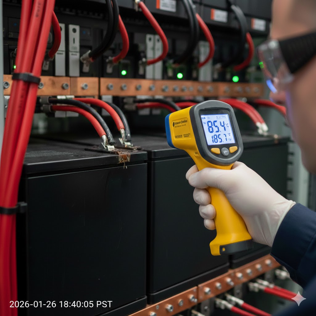
15.1 One battery getting hotter than others

Heat is the #1 indicator of resistance or over-work. In a perfectly balanced bank, all batteries should be within a few degrees of each other.

If one battery is significantly hotter:

  • In Parallel: This battery is likely doing more work than the others. Check the wiring resistance. Is the cable to this battery shorter? Are the connections cleaner? It’s “hogging” the current.

  • In Series: This battery likely has higher internal resistance (it’s failing). It is struggling to pass the current that the rest of the string is pushing through it.

  • The Terminal Test: Safely touch (or use an IR thermometer on) the terminal post itself. If the post is hot but the battery case is cool, you have a loose connection. Tighten the nut immediately.

15.2 Uneven voltage readings

Grab your multimeter. This is your primary diagnostic tool.

In Series Strings (e.g., 4 x 12V = 48V): Measure each battery individually while the system is under load (discharging).

  • Good: All batteries read ~12.8V.

  • Bad: Battery A is 11.5V, while B, C, and D are 13.2V.

    • Diagnosis: Battery A is empty or dead. The others are trying to “reverse charge” it. Stop immediately and charge Battery A individually.

In Parallel Strings: They should theoretically all be the same voltage because they are connected.

  • Test: Disconnect the batteries from each other and let them sit (rest) for an hour. Then measure.

  • Diagnosis: If one battery settles at 12.6V while the others are at 13.4V, that battery has a self-discharge issue or an internal short. It is a “parasite” draining the others.

15.3 Batteries not charging equally

You charge the bank all day, but the “Full” light never comes on, or the capacity drops instantly when you use it.

The Cause: wiring Asymmetry. We discussed the “Diagonal Take-off” in Section 10. If you ignored that and wired “Daisy Chain” style, the last battery in the line never gets fully charged.

  • The Fix: You cannot fix this with software. You must rewire the bank. Ensure every battery sees the exact same cable length to the main charging source.

  • The Band-Aid: If you can’t rewire, you must periodically disconnect the batteries and charge each one individually with a 12V charger to bring them back in line.

15.4 BMS shutting down unexpectedly

This is a common complaint with modern Lithium (LiFePO4) systems. The lights go out, wait 30 seconds, and come back on.

Scenario A: Inrush Current You turn on a 3000W inverter. The capacitors inside gulp power instantly. The surge exceeds the BMS “Peak Discharge” limit (e.g., 300A for 3ms).

  • Fix: You need a “Pre-charge Resistor” circuit to fill the capacitors slowly before flipping the main switch.

Scenario B: Single Cell Trigger The bank voltage looks fine (13.4V), but the power cuts.

  • Cause: Inside the battery, one specific cell hit 3.65V (Over-voltage) or 2.50V (Under-voltage) before the others. The BMS protects that single cell by killing the whole pack.

  • Fix: This indicates a severe imbalance. The battery needs to be fully discharged and recharged slowly to allow the internal balancer to do its job.

16. Final Summary

We have covered a lot of ground, from the physics of electron flow to the specific torque specs of a busbar. If you take nothing else away from this guide, remember these four core principles. They are the difference between a reliable power system and a fire hazard.

16.1 Series = more voltage

Connecting in series stacks the electrical pressure.

  • The Goal: Efficiency. High voltage pushes current easily, allowing you to run heavy loads (AC, large inverters) with thinner wires and less heat.

  • The Trade-off: Capacity (Ah) stays the same. You don’t get “more” battery; you just get a “stronger” battery.

  • The Rule: Use series when your power needs exceed 2,000 Watts.

16.2 Parallel = more capacity

Connecting in parallel widens the fuel tank.

  • The Goal: Endurance. You want to run your lights and fridge for three days instead of one.

  • The Trade-off: Voltage stays the same. You are limited to the power constraints of lower voltage (thick cables, high current).

  • The Rule: Use parallel when you need runtime but want to keep your existing 12V appliances.

16.3 Correct wiring = longer battery life

Batteries do not die naturally; they are murdered by bad wiring.

  • Resistance is the Enemy: A loose crimp or a cable that is 6 inches too long creates resistance.

  • Imbalance Kills: Resistance causes one battery to work harder than the others. That battery fails early, and the rest follow shortly after.

  • Symmetry Wins: Whether it is the “Diagonal Take-off” or using a busbar, the goal is to make every electron travel the exact same distance.

16.4 Safety and balance matter more than theory

You can calculate voltage drop on paper all day, but physics happens in the real world.

  • Fuses are Mandatory: Not just for code, but to save your life. A battery shorting out without a fuse is an arc welder.

  • Match Your Cells: Never mix old and new, or Lithium and Lead-Acid. The chemistry will fight, and the weaker battery always loses.

  • Respect the Specs: If a manufacturer says “Max 4 in Series,” believe them. They know the limits of their internal components better than you do.

Building a battery bank is about respect—respect for the energy stored inside these chemical blocks. wire it right, fuse it properly, and it will run your rig for a decade. Wire it sloppy, and you’ll be buying new batteries next season.

Related Events

Contact Us

Contact Us 2
First
Last

Do you have a project that needs a custom battery pack?